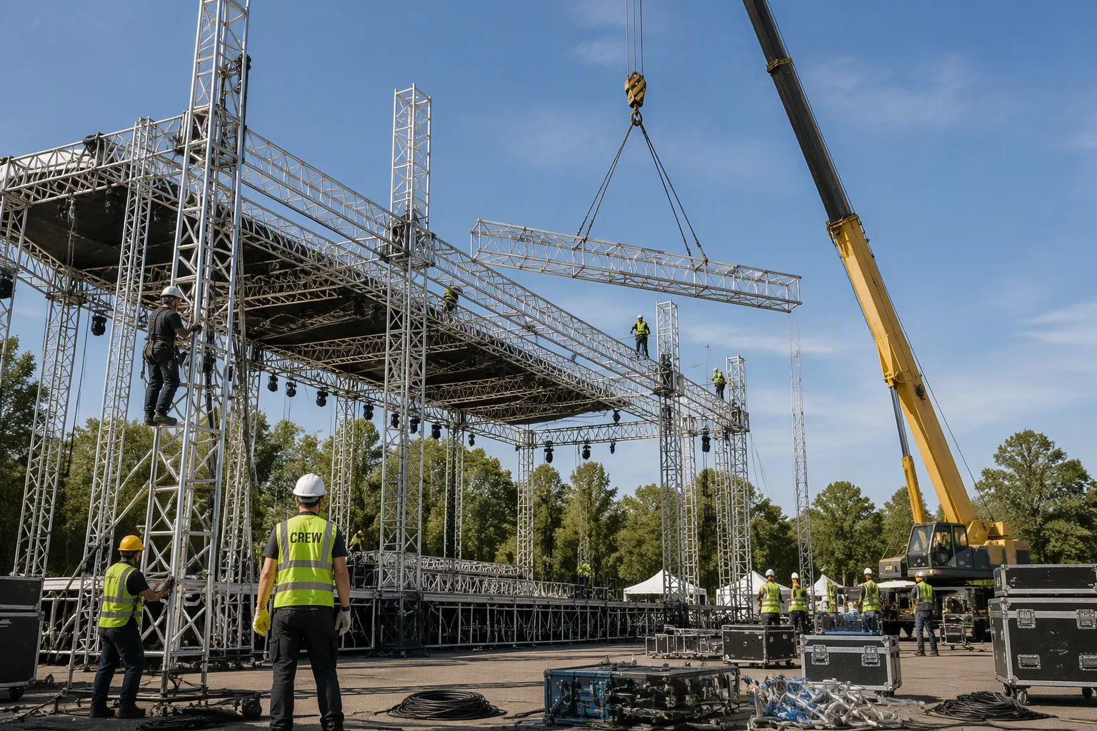
You need a fully engineered structure for a 20m outdoor concert stage truss. Verified load calculations, durable materials, controlled fabrication, and safe assembly matter. Every load path—roof dead load, live equipment loads, wind uplift, rigging loads, and ballast—must be defined before fabrication. GF-Truss supplies modular aluminum systems with corrosion-resistant finishes and documented load ratings.
Key Takeaways
- Engineering comes first. A licensed engineer calculates all loads and designs the truss system. This ensures safety and gets permits approved.
- Production uses certified materials and processes. Factories build truss parts with precision. Quality checks guarantee strong and durable components.
- Installation requires careful planning and execution. You prepare the site, place ballast correctly, and follow safety checks. This leads to a successful concert.
Design and Engineering for a 20m Outdoor Concert Stage Truss
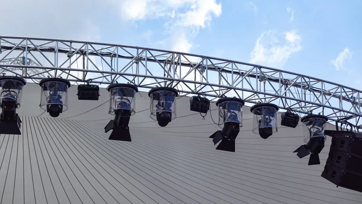
Engineering drives every decision on a 20m outdoor concert stage truss. You cannot guess at loads, pick components from a catalog, and hope the structure holds. A licensed structural engineer leads this phase. The engineer studies your site, calculates every force, selects the right system, and documents the design for permitting and fabrication.
- Project Scope, Site Conditions, and Permitting Constraints
You start with the project scope. Define the stage width, roof coverage, trim height, and rigging capacity. A 20m span typically supports a roof system with a front-of-house position, side wings, and a back wall. The promoter provides the artist's rider. That rider lists lighting, audio, video, and special effects equipment. Each item adds weight and power demand.
Site conditions shape the design. You measure wind exposure, ground slope, soil bearing capacity, and nearby obstructions. An open field exposes the stage to full wind pressure. A downtown plaza creates wind tunnels between buildings. Both scenarios demand different ballast and anchoring strategies. Permitting constraints vary by jurisdiction. Most local authorities require a sealed engineering package before they issue a staging permit. That package includes structural drawings, load calculations, and a site plan. Some venues add noise ordinances, curfews, and fire marshal inspections. You submit early. Late submissions delay the entire project.
- Load Calculations: Wind, Dead, Live, and Seismic
Load calculations determine whether your outdoor concert stage truss survives opening night. The engineer evaluates four load categories. Each category interacts with the others. Dead load covers the permanent weight of the structure itself. Aluminum truss, roof panels, cladding, and fixed accessories all contribute. You sum these weights along every load path.
Live load includes temporary equipment and personnel. Lighting rigs, speaker arrays, LED walls, and cable bundles add significant mass. The engineer applies dynamic amplification factors for moving loads. Stage crews walking on the roof grid also count as live load. Wind load dominates outdoor design. The engineer calculates wind pressure using ASCE 7 or the local building code. Wind speed, exposure category, and roof height all affect the result. Uplift forces can exceed the roof's dead weight. You counter uplift with ballast or ground anchors.
Seismic load matters in active regions. The engineer checks lateral forces against the structure's base connections. Even moderate seismic zones require lateral bracing and ductile connections.
- Structural System Selection: Roof Truss, Towers, and Ballast
System selection follows the load calculations. You choose a roof truss configuration that spans 20m without excessive deflection. Common options include flat roof grids, pitched roofs, and arched designs. Each option offers different rigging points and aesthetic profiles.
Towers support the roof truss. You select tower height, base dimensions, and connection details. Modular tower systems allow height adjustment on site. That flexibility helps when the venue has uneven ground.
Ballast keeps the structure grounded. You calculate ballast weight from wind uplift and overturning moments. Concrete blocks, water tanks, and ground anchors serve as ballast options. The engineer specifies the exact weight and placement for each tower base.
GF-Truss provides modular aluminum systems that adapt to these requirements. Their roof truss, tower, and ballast components integrate cleanly. Documented load ratings simplify the engineer's verification work.
- GF-Truss Materials, Components, and Connections
Material quality determines the structure's service life. GF-Truss builds its systems from 6082-T6 aluminum alloy. This alloy offers high strength-to-weight ratio and excellent corrosion resistance. The extrusion process produces hard pressed extruded aluminum with consistent wall thickness.
Certifications validate the material and manufacturing process. The table below summarizes the key standards.
|
Aspect |
Specification |
|---|---|
|
Material |
6082-T6 aluminum alloy |
|
Extrusion standard |
Hard pressed extruded aluminum |
|
Certifications |
CE, TUV, SGS, ISO9001 |
|
Application |
Outdoor stage roof truss system |
Connections matter as much as the chords and diagonals. GF-Truss uses precision-machined couplers, conical connectors, and high-grade steel pins. These components transfer loads efficiently and resist vibration. You assemble and disassemble the system repeatedly without losing connection integrity.
Corrosion protection extends the truss life in outdoor environments. GF-Truss applies anodized or powder-coated finishes. These finishes resist moisture, salt, and UV exposure. You get a system that performs reliably season after season.
The engineering phase ends with a complete design package. That package includes general arrangement drawings, load calculations, connection details, and ballast plans. You review the package with your engineer and the venue. Approval triggers the production phase.
Production and Fabrication of the Outdoor Concert Stage Truss
- Shop Drawings, Approvals, and Procurement
You convert the approved design into shop drawings before any metal gets cut. These drawings break the structure into identifiable chord sections, web members, plates, and connection components. Each part carries a piece mark that links to material certificates, inspection records, and packing lists. The building designer reviews and approves both the truss placement diagram and individual truss design drawings. You assemble the full submittal package—structural drawings, load schedules, welding requirements, and release documents—and secure approval before releasing fabrication.
- Welding, Machining, Finishing, and Corrosion Protection
Fabrication demands certified processes and skilled labor. GF-Truss holds CE, ISO9001, TUV, and SGS certifications. Their factory uses CNC technology for precise cutting, welding, and shaping. Semi-automated jigs improve alignment and accuracy during assembly.
|
Category |
Required before fabrication |
|---|---|
|
Certifications |
CE, ISO9001, TUV, SGS |
|
Production processes |
Stress tests, structural analyses, load-bearing tests, CNC technology, semi-automated jigs |
Weld repairs, in particular, should be performed by an AWS certified welder.
You verify welding methods and inspection scope against project documents. Ultrasonic inspection detects internal cracks and porosity. Dye penetrant inspection reveals surface-breaking defects. For corrosion protection, consider powder coating or anodizing for added durability and a custom look. Aluminum naturally forms a protective oxide layer. Anodized or powder-coated finishes further resist moisture, salt, and UV exposure.
- Quality Control, Proof Load Testing, and Inspection
Quality control runs through every production stage. You require material certificates, dimensional reports, welding records, NDT reports, and coating inspection records. Third-party load test reports provide independent verification of structural performance. A TUV load test certificate confirms safety compliance. Weld inspection records document NDT and weld quality checks. You review all documentation before the structure leaves the factory.
- Packing, Marking, and Shipping Logistics
You use a single piece-mark system across all drawings, members, inspection records, and packing documents. Surface protection prevents damage during transport. You confirm transport limits and delivery destination. Proper packing and clear marking speed up on-site assembly for your outdoor concert stage truss.
Installation, Safety, and Delivery of the 20m Outdoor Concert Stage Truss
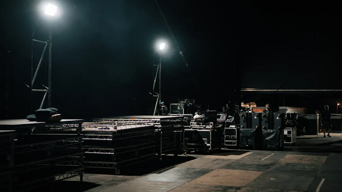
Installation turns your engineered drawings into a standing structure. You cannot rush this phase. Every step—from ground preparation to final sign-off—demands discipline and verification. A single missed anchor or misplaced ballast block can compromise the entire outdoor concert stage truss. You follow the assembly manual, you check every connection, and you document every decision.
- Site Preparation, Foundations, and Ballast Placement
You begin with the ground itself. The soil must support the tower base loads without settlement. You clear the site of debris, level the surface, and compact loose soil. If the ground cannot bear the load, you pour concrete pads or use steel spreader plates. You mark the tower positions with survey stakes. These stakes must match the general arrangement drawings exactly.
Ballast placement follows the engineered drawings without deviation. You verify ballast quantity by measurement, not assumption. A deviation of even 2 ft can reduce wind resistance by changing the lever arm in the overturning calculation. You place ballast in the exact positions shown on the drawings. You secure each block so it cannot shift. Water ballast must be completely full before each use. You never remove or relocate ballast without engineering approval.
The table below summarizes how different ballast methods prevent specific failure modes.
|
Failure mode |
Anchoring/ballast method |
Key specification |
|---|---|---|
|
Uplift (vertical force) |
Use removable heavyweight ballast tied to the structure with taut wire ropes; wire ropes in many designs are at 45 degrees |
The vertical component of the rope tension is resisted by ballast weight; required weight is the uplift force multiplied by a design safety factor, often 1.5 under the applicable code |
|
Sliding (horizontal force) |
Add enough ballast weight to resist the horizontal component through friction with the supporting surface |
Friction coefficients between concrete and wet ground, grass, or plywood are typically 0.3 to 0.4; horizontal resistance equals ballast weight times the friction coefficient, so the required weight is often almost 3 times the horizontal force |
|
Overturning |
Anchor the wire rope to a low and wide ballast, never a tall thin element |
The tie point location is critical; a high attachment can make the ballast tip over |
|
Stability during wind events |
Keep ballast secure and verify friction assumptions, especially on wet ground |
If ballast slides, wire rope slackens or breaks, causing the tower top to move and increasing stress in the roof supports |
You choose the ballast type based on site conditions and project duration. Concrete ballasts work well when ballast can remain until loadout. Water ballasts suit projects that need quick drainage and removal. UNI-BLOC ballasts offer a prefabricated option for ground-supported stages and offset structures. The table below outlines placement methods and typical uses.
|
Ballast type |
Placement/anchor method |
Typical use |
|---|---|---|
|
Concrete ballasts |
Large forklift-moved blocks; commonly lifted and anchored with steel and straps at a top rebar anchor point |
Place next to the stage, outside the stage footprint, or on planks in the stage baseout near planned vertical tower locations; suitable where ballast can remain until loadout |
|
Water ballasts |
Portable water-filled basins; must be completely filled and verified |
Useful when ballast needs to be drained and moved quickly |
|
UNI-BLOC ballasts |
Prefabricated ballast units in two sizes; position and anchor them according to the engineered layout |
Good for ground-supported stages and offset structures such as delay towers and video hangs |
You arrange ballast to resist lateral pressure. Wind hitting the front or side pushes the structure sideways. This push strains columns and masts. Correct placement keeps the ballast horizontal resistance in line with that push. You confirm water ballast is full before each use. You verify ballast quantity by measurement instead of assumption. These steps keep the resisting moment large enough for the design wind load.
- Crane Selection, Rigging Plan, and Ground-Build Assembly Sequence
You select the crane based on the heaviest roof section and the maximum reach required. The crane must have enough capacity at the working radius to lift each truss segment safely. You check ground bearing pressure under the crane outriggers. Soft ground requires crane mats or steel plates. You confirm the crane operator holds current certifications for the lift.
The rigging plan defines every sling, shackle, and lifting point. You calculate sling angles and tension forces. You inspect all rigging hardware before the lift. Damaged or worn components go back to the shop. You mark the center of gravity on each roof section. The crane operator uses this mark to balance the load during the lift.
You assemble the stage roof on the ground whenever possible. Ground-build assembly reduces work at height and improves safety. You build the roof truss in sections, then lift each section into place. You connect the sections at the tower tops. You follow the assembly sequence in the manual. The sequence prevents unbalanced loads during construction. You never skip a step to save time.
- Rigging Checks, Tensioning, and Final Alignment
You perform rigging checks after every lift. You inspect shackles, slings, and connection pins for proper seating. You verify that all safety clips are engaged. You check wire rope tension on ballast lines. Slack lines allow tower movement. You tension each line to the specified value. You use a tension meter or turnbuckle gauge to confirm the load.
Final alignment ensures the structure matches the design geometry. You measure tower plumbness with a level or laser. You check roof truss deflection under dead load. You compare measured deflection against the calculated value. Excessive deflection signals a problem. You investigate before adding live load. You torque all structural bolts to the specified value. You mark each bolt with a paint stripe after tightening. This mark lets inspectors verify that no bolt loosened during assembly.
You document every check on a sign-off sheet. The sheet lists each connection, each tension value, and each alignment measurement. You photograph critical connections before covering them. These records protect you if questions arise later.
- Permits, Risk Assessments, and Structural Sign-Off
You secure all permits before the first truck arrives on site. The staging permit, electrical permit, and fire marshal approval must be in hand. You post copies at the site office. You brief the crew on permit conditions. Noise curfews and load-in windows affect your schedule. You plan around them.
A written risk assessment identifies every hazard and control measure. You list fall protection, crane exclusion zones, electrical safety, and weather monitoring. You assign a competent person to monitor wind speed. You set a wind speed limit for stopping work. You train the crew on emergency procedures. You conduct a safety meeting before each shift.
Structural sign-off happens after final alignment and tensioning. A licensed engineer inspects the completed structure. The engineer compares as-built conditions against the design drawings. Any deviation requires review and approval. The engineer signs the completion certificate. You keep this certificate on site. You do not allow any load on the roof until sign-off is complete.
- Cost Drivers, Lead Times, and Final Deliverables
Several factors drive the total project cost. Truss span and roof complexity top the list. A 20m span with a pitched roof costs more than a flat roof grid. Wind speed requirements affect ballast weight and anchoring complexity. Site access determines crane size and rigging time. Permitting fees vary by jurisdiction. You budget for engineering, fabrication, transport, installation labor, and equipment rental.
Lead times depend on design approval and factory scheduling. Standard GF-Truss components ship faster than custom fabrications. You allow four to eight weeks for production after drawing approval. Shipping time adds one to three weeks depending on destination. You book cranes and labor crews early. Peak concert season fills available resources quickly.
Final deliverables include the complete engineering package. You receive the FEA report, general arrangement drawings, anchor and ballast plans, and the assembly manual. You get material certificates, weld inspection records, and load test reports. GF-Truss provides installation guidance and technical support. You archive all documents for future projects. These records simplify permitting for repeat events.
You deliver a successful outdoor concert stage truss through engineering-first design, controlled production, and disciplined site execution. Require the full engineered package—FEA report, general arrangement drawings, anchor and ballast plans, and assembly manual—before you approve fabrication. Request an engineered truss design package from GF-Truss or consult a structural engineer and rigging specialist before you lock dates.
FAQ
Q: How do I calculate wind load for a 20m outdoor stage truss?
A: You use ASCE 7 or your local building code. Wind speed, exposure category, and roof height determine the result. An engineer must verify uplift forces against your ballast plan.
What ballast do I need for wind uplift?
You place concrete, water, or UNI-BLOC ballast exactly where the drawings specify. You multiply the uplift force by a safety factor, often 1.5, to determine the required weight.
What documents do I receive before installation?
You receive an FEA report, general arrangement drawings, anchor and ballast plans, and an assembly manual. GF-Truss also provides material certificates and load test reports for permitting.