Aluminum truss systems are widely used for stage structures, exhibition displays, lighting rigs, and LED screen support. Although modular trusses are designed for efficient assembly, installation mistakes can affect structural stability, connection reliability, and the overall safety of an event setup.
Some problems are easy to overlook during installation. A connector that does not fully engage, an uneven base, or an incorrect load arrangement may create risks that are not immediately visible. Understanding these issues before assembly helps installation teams avoid unnecessary adjustments and build a more reliable structure.
This guide explains common aluminum truss installation mistakes, why they matter, and how to prevent them in practical stage and event applications.
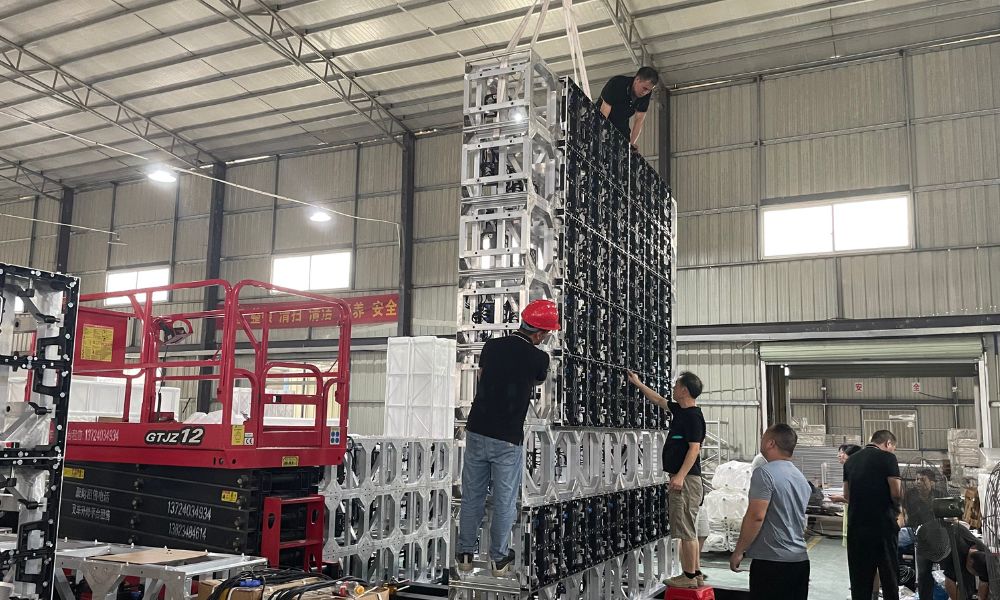
Aluminum truss and LED screen support installation at a project site.
Why Proper Aluminum Truss Installation Matters
An aluminum truss structure works as a connected structural system. Its performance depends not only on the individual truss sections but also on connection components, support conditions, bracing arrangements, applied loads, and the accuracy of the installation process.
Even a high-quality truss cannot compensate for an incorrectly assembled structure. For example, a connection that is not fully secured may affect load transfer between sections, while an inadequately prepared support surface can introduce unwanted movement or uneven forces.
GF-Truss provides aluminum spigot trusses, bolt trusses, custom-shaped trusses, accessories, and complete truss systems. Because different configurations use different connection and support components, installation procedures should always follow the approved drawings and specifications for the actual system.
Using Incompatible Connectors or Hardware
One common installation mistake is mixing truss sections, pins, bolts, or other connection components that are not designed to work together. Components may look similar in size, but small differences in connection geometry or dimensions can prevent proper engagement.
For example, spigot connections and bolt connections use different assembly methods. A pin-and-connector arrangement should not be treated as interchangeable with a bolted connection simply because the truss sections have similar external dimensions.
How to avoid this mistake:
- Confirm the truss series, dimensions, and connection type before installation.
- Use the specified pins, bolts, clips, and accessories supplied or approved for the system.
- Check that connection components are not bent, cracked, excessively worn, or otherwise damaged.
- Do not modify or substitute hardware without technical approval.
GF-Truss offers different aluminum truss accessories for structural connections and system configurations. Selecting compatible components from the beginning helps reduce assembly problems on site.
Forcing Connections When Truss Sections Do Not Align
Another frequent mistake is forcing two truss sections together when their connection points do not align naturally. Installers may try to push, pull, or hammer components into position to save time. This approach can damage connection areas, distort components, or conceal an underlying alignment problem.
Misalignment can result from incorrect positioning, unsuitable components, uneven support conditions, or a difference between the actual assembly and the approved drawings.
How to avoid this mistake:
- Check the orientation and sequence of each truss section before connecting it.
- Make sure the connection faces are correctly positioned and free from obstructions.
- Recheck the layout and support positions if connection points do not line up.
- Never use excessive force to make incompatible or misaligned components fit.
If a connection cannot be completed using the intended assembly method, stop and identify the cause before proceeding. Repeatedly forcing a connection can turn a simple installation issue into a component replacement or structural inspection problem.
Ignoring Base Leveling and Ground Conditions
A truss structure is only as reliable as the support conditions it is designed to work with. Installing a tower or ground-supported structure on an uneven, soft, or unsuitable surface can affect vertical alignment and load distribution.
This issue is particularly important for ground support systems and tall structures. If the base is not positioned and leveled according to the design, the structure may develop unwanted inclination or instability.
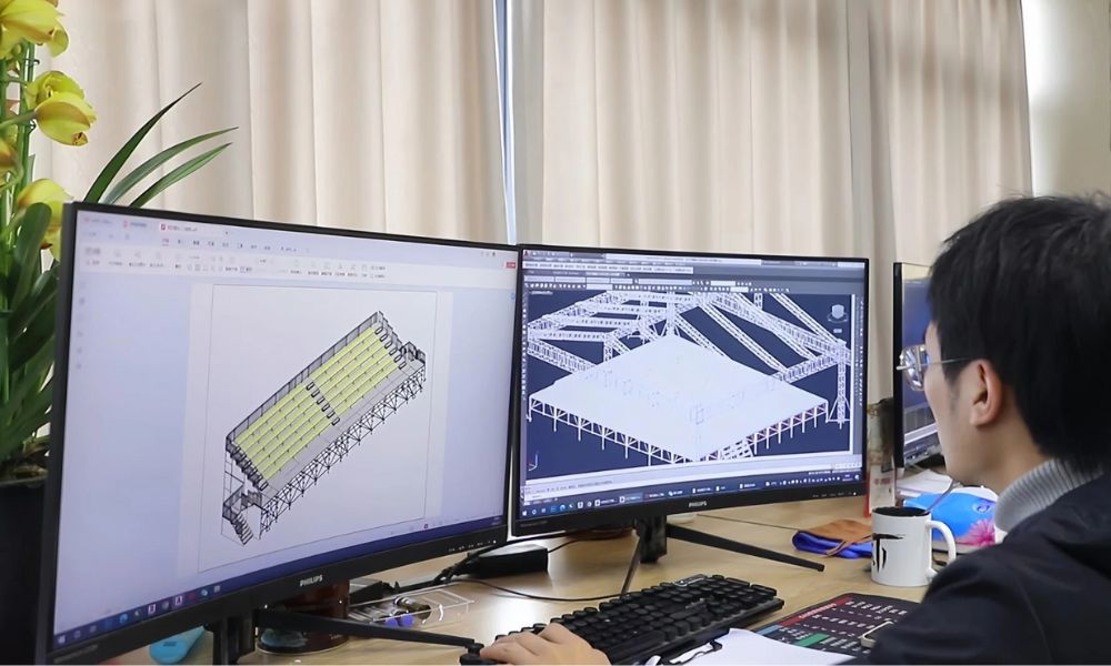
Reviewing structural layouts before installation helps identify positioning and support requirements.
How to avoid this mistake:
- Inspect the installation surface before positioning the structure.
- Use the specified base plates, ground beams, and leveling components.
- Check vertical alignment and base positioning during assembly.
- Confirm that the supporting ground can accommodate the loads required by the structural design.
For tower-based configurations, compatible base components and lifting accessories are especially important. GF-Truss provides different aluminum truss systems, including tower and roof systems, which should be installed according to their specific structural arrangements.
Assembling the Structure in the Wrong Sequence
Installing truss sections in an unsuitable order can make later connections difficult and create unnecessary temporary instability. This often happens when crews begin assembling components without reviewing the complete layout or identifying the correct installation sequence.
Large roof structures, tower systems, and multi-section stage frames require coordinated assembly. Their installation sequence should account for support positions, connection locations, temporary stability, and the lifting method specified in the construction plan.
How to avoid this mistake:
- Review the approved CAD drawings and assembly instructions before work begins.
- Identify the main support points, structural sections, and connection locations.
- Assign clear responsibilities to installation team members.
- Follow the specified lifting and temporary stabilization procedures.
- Do not remove temporary supports until the required permanent connections and stability checks are complete.
For customized projects, GF-Truss provides CAD design and detail confirmation before production. Its optional factory trial assembly service also allows customers to review dimensions, connections, and the overall structure before shipment, helping identify potential installation issues earlier.
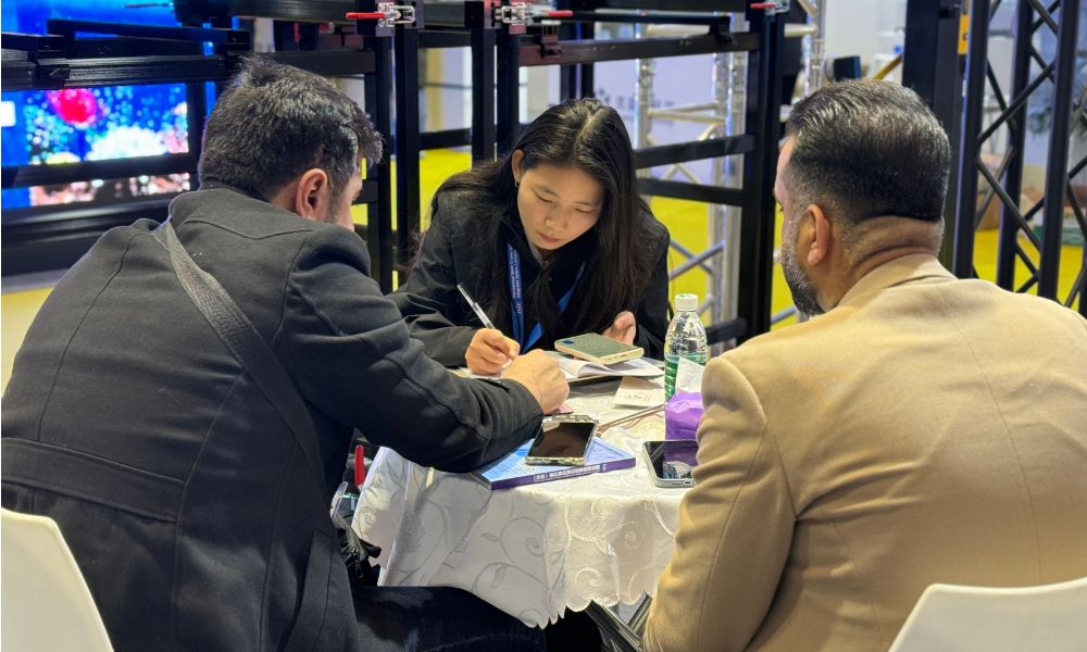
Project requirement discussions help clarify structural details before production and installation.
Distributing Loads Incorrectly Across the Truss
Incorrect load distribution is a serious installation concern, especially for lighting rigs, concert stages, and LED screen support structures. A truss may be designed for a specific load arrangement, but placing equipment in different positions or adding unplanned loads can change the forces acting on the structure.
For example, concentrating several heavy lighting fixtures in one area instead of following the approved loading plan may create localized forces. Adding equipment after the original structural design has been approved can also exceed the assumptions used in the engineering calculations.
How to avoid this mistake:
- Confirm the total equipment weight and its installation positions.
- Follow the approved load plan and manufacturer specifications for the exact truss configuration.
- Consider the effects of suspended equipment, accessories, and other attached components.
- Have a qualified structural professional review any proposed changes to the original loading arrangement.
- Never assume that two trusses with similar dimensions have the same load capacity.
Load capacity depends on factors such as truss model, material, span, support conditions, connection details, and load distribution. Always use the relevant technical documentation and engineering calculations rather than relying on a general capacity figure.
Overlooking Wind Loads and Outdoor Stability
Outdoor installations introduce additional considerations that may not apply to indoor structures. Wind can act on the truss itself as well as on attached elements such as LED screens, banners, roof coverings, and decorative panels.
A structure that appears stable under normal conditions may experience significantly different forces when exposed to changing wind conditions. Insufficient ballast, unsuitable anchoring, or an unapproved configuration can increase the risk of movement or overturning.
How to avoid this mistake:
- Determine whether the installation is intended for indoor or outdoor use.
- Check the project-specific wind design requirements and site conditions.
- Use the specified ballast, anchoring, and support arrangements.
- Consider the wind exposure of attached screens, banners, and roof elements.
- Follow the event safety plan for weather monitoring, restricted operation, and shutdown conditions.
GF-Truss offers customized roof systems and LED wall support solutions for different project configurations. For outdoor applications, the structural design should be confirmed according to the actual screen dimensions, wind conditions, ballast requirements, and installation environment.
For projects involving large displays, reviewing the relevant LED wall support solutions can help clarify the required support arrangement and installation considerations.
Failing to Check LED Screen Alignment and Connection Details
LED wall support installations require more than simply connecting the main truss sections. The positioning of support beams, screen cabinets, locating pins, and adjustment components can all affect the final display alignment.
If the supporting structure is not properly aligned, LED cabinets may not sit evenly. Installers may then attempt to compensate by adjusting individual connections, which can create additional problems if the underlying support structure has not been checked.
How to avoid this mistake:
- Confirm the screen dimensions, cabinet arrangement, and support layout before assembly.
- Check the position and compatibility of locating pins and connection components.
- Use appropriate leveling and alignment tools during installation.
- Inspect the complete support structure before mounting or loading the LED cabinets.
Some GF-Truss LED support products include alignment-related design features. For example, its OLED wall panel ground and hanging support product incorporates an integrated level gauge to help installers check horizontal alignment. The exact installation procedure should still follow the documentation for the selected model.
Skipping the Final Inspection Before Use
A structure should not be considered ready simply because all visible sections have been connected. Skipping the final inspection can allow loose hardware, incomplete connections, incorrect component placement, or unexpected deformation to go unnoticed.
How to avoid this mistake:
- Check every connection against the approved assembly drawings.
- Verify that pins, clips, bolts, and other specified hardware are correctly installed.
- Inspect truss members and connection areas for visible damage or deformation.
- Confirm that bases, supports, bracing, and stabilizing components are in their specified positions.
- Verify that the installed structure matches the approved load arrangement.
- Record inspection results and resolve any outstanding issues before the structure is put into service.
GF-Truss offers product inspection and optional trial assembly services before shipment. These steps allow customers to verify product quantity, quality, dimensions, and connection details before the equipment reaches the installation site.
Aluminum Truss Installation Checklist
A consistent inspection routine can help installation teams reduce avoidable mistakes. The following checklist provides a practical reference for project preparation and on-site verification. It does not replace the approved engineering documents or the manufacturer's installation instructions.
| Inspection Stage | What to Check | Purpose |
|---|---|---|
| Before installation | Drawings, dimensions, truss models, and connection types | Prevent component mismatch |
| Component inspection | Truss members, pins, bolts, clips, and accessories | Identify damaged or unsuitable parts |
| Base preparation | Ground conditions, base position, and leveling | Establish suitable support conditions |
| Assembly | Connection engagement, assembly sequence, and bracing | Maintain the intended structural arrangement |
| Load installation | Equipment weight, load positions, and wind requirements | Avoid unapproved loading conditions |
| Final inspection | Connections, alignment, supports, and visible damage | Confirm readiness for use |
How GF-Truss Helps Reduce Installation Problems
Installation quality starts well before the equipment arrives at the venue. Clear technical communication, accurate drawings, compatible components, and pre-shipment checks can help reduce uncertainty during on-site assembly.
GF-Truss provides customized aluminum truss and LED wall support solutions. Its project service process includes requirement discussions, CAD design, detail confirmation, production, product inspection, and optional trial assembly.
For customized projects, customers can provide key information such as application scenarios, product dimensions, required load capacity, connection methods, and shape requirements. This information helps the design team prepare a solution that matches the intended installation conditions.
By confirming structural details before production and checking connections through optional trial assembly, project teams can identify potential issues earlier and prepare more effectively for installation.
Checking the assembled structure and its connections is an important part of project preparation.
Frequently Asked Questions About Aluminum Truss Installation
What is the most common mistake when installing aluminum trusses?
Using incompatible connection components, failing to align truss sections correctly, and overlooking base leveling are common installation mistakes. Each component should match the approved truss system and assembly drawings.
Can different aluminum truss connection systems be mixed?
Not automatically. Spigot and bolt trusses use different connection methods. Components should only be combined when their compatibility has been confirmed by the manufacturer or a qualified structural professional.
Why is leveling important when installing a truss tower?
Proper leveling helps establish the intended support conditions and vertical alignment. An uneven base can introduce unwanted movement or uneven forces, so the ground and base arrangement should be checked before the structure is raised or loaded.
How can installers prevent aluminum truss connection problems?
Check the truss series, connection type, and hardware before assembly. Inspect pins, bolts, and connector surfaces, and never force components together when the connection points do not align naturally.
What should be checked before using an assembled aluminum truss structure?
Inspect all connections, supports, bracing, base positions, visible structural conditions, and equipment loading arrangements. The completed structure should be checked against the approved drawings and relevant engineering requirements before use.
Does GF-Truss provide support for customized truss installation projects?
GF-Truss provides customized project services including CAD design, detail confirmation, product inspection, and optional factory trial assembly. On-site guidance or assistance may also be available depending on project requirements.
Can outdoor aluminum truss systems be installed without additional stabilization?
Not necessarily. Outdoor stability depends on the structure, wind exposure, attached equipment, ground conditions, and engineering design. Ballast, anchoring, and other stabilization measures should follow the project-specific structural requirements.
Proper aluminum truss installation is a combination of correct component selection, accurate assembly, suitable support conditions, controlled loading, and thorough inspection. By addressing these details before and during installation, project teams can reduce avoidable errors and improve the reliability of stage, exhibition, and LED support structures.
If you are planning a customized aluminum truss project, contact GF-Truss to discuss your dimensions, connection requirements, application conditions, and structural design needs.