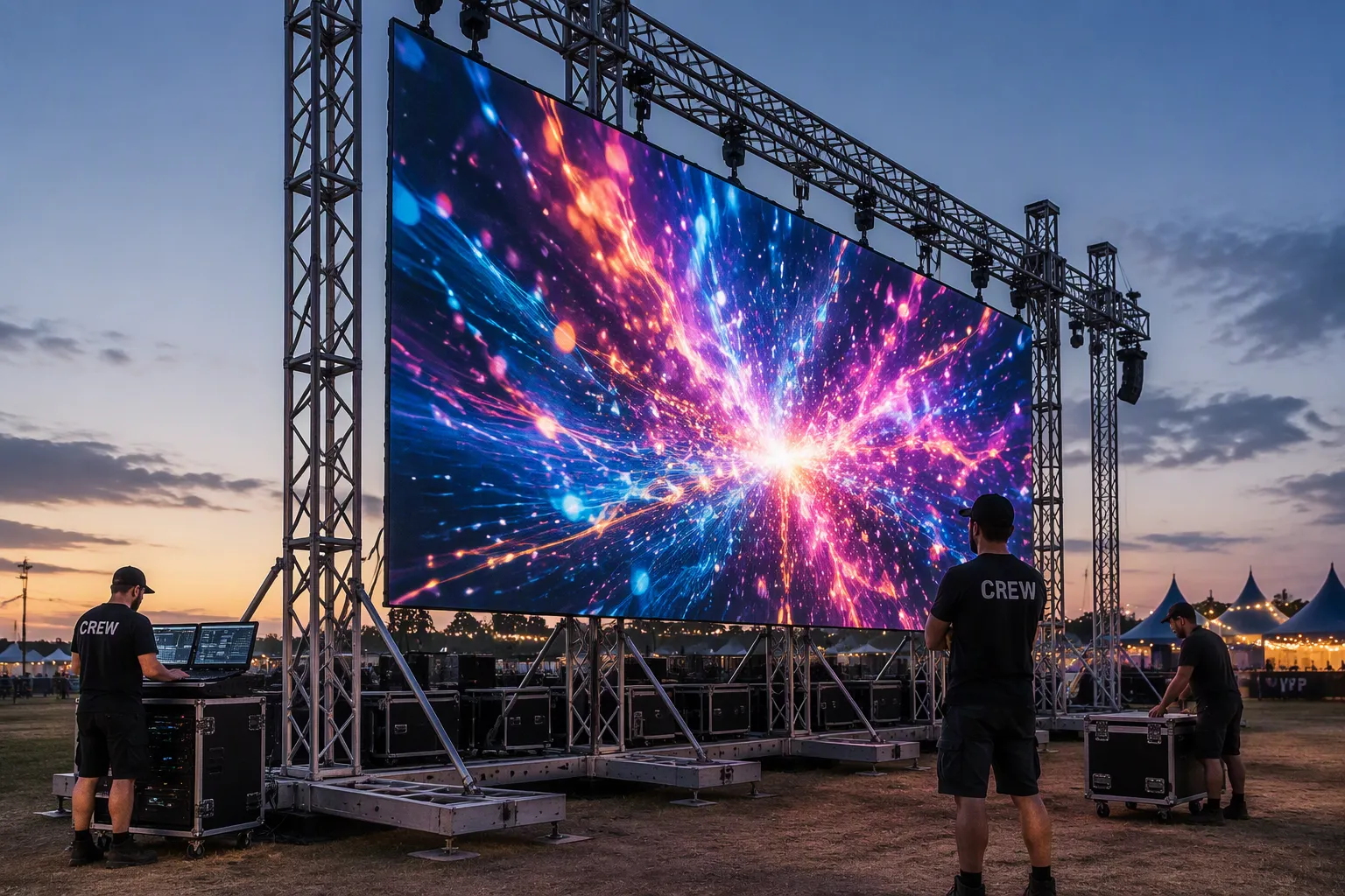
An LED wall ground support system is a freestanding, self-supporting structure that holds LED panels without attachment to a building or roof. Its core purpose is to position and stabilize LED video walls safely at outdoor events. Choose a ground support system when your site lacks rigging points or suitable walls for an LED wall support system.
Key Takeaways
- Ground support systems hold LED walls without attaching to buildings. They work well for outdoor events with no rigging points.
- Proper ballast and wind monitoring keep the structure safe. Always follow the manufacturer's ballast chart and wind limits.
- Plan your system around screen size, ground conditions, and permits. A complete design prevents accidents and saves time.
What Is an LED Wall Support System?
- Definition and Core Purpose
An LED wall support system is the complete structural package that holds LED panels in position and keeps them stable during an event. You can think of it as the frame that turns a stack of video panels into a single, safe display. The system carries the weight of the screen, resists wind and other forces, and keeps the viewing surface aligned. Every component works together to protect both the audience and the equipment.
- Ground Support vs. Hanging vs. Wall-Mounted
You have three main ways to support an LED wall, and each one fits different site conditions. A ground support system stands on its own base and needs no building attachment. A hanging system suspends the wall from overhead rigging points, such as a roof beam or a truss grid. A wall-mounted system fastens the panels directly to a building facade or interior wall.
Ground support makes sense when your site has no rigging points, no suitable wall, or limited load capacity overhead. Hanging works well in venues with certified rigging. Wall mounting suits permanent or semi-permanent installations. For outdoor events on open ground, ground support usually offers the most control and the fewest site dependencies.
Whatever type you select, confirm that the structure meets recognized engineering standards. The table below summarizes the key standards and certifications that apply to outdoor LED wall support systems.
| Standard / Certification | Details |
|---|---|
| TUV Certified Welding | Third-party certification body and Nationally Recognized Testing Laboratory (NRTL) providing inspection, testing, and certification for reliability, safety, and quality |
| EN-AWT6 6082 Aluminum | Material standard used in manufacturing for safety and strength |
| Engineering Drawing Compliance | Ballast and guy wire assembly must be installed per engineering drawings to meet certification requirements |
| Industry-Standard Dimensions | Truss utilizes standard conical connector system compatible with other F34 trussing products of same size/connector type |
Key Components of Ground Support Systems
A reliable LED wall support system combines four building blocks: a weighted base, truss towers and beams, panel mounting hardware, and wind safety accessories. Each part shares the load and keeps the screen stable.
- Base and Ballast
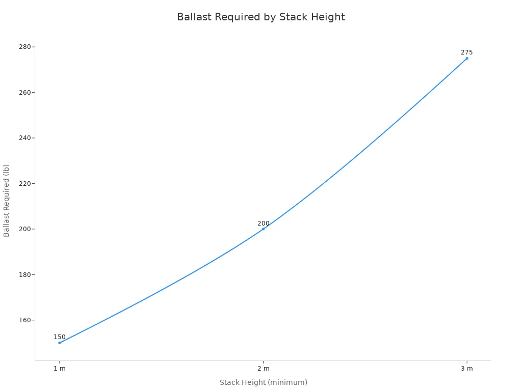
The base anchors the entire structure. Adjustable bases often use aluminum alloy 6061-T6 with a 50×3 mm main tube and 150×500×1000 mm dimensions, supplied in sets of eight. Ballast requirements rise with screen height, so plan weights early.
| Stack Height (minimum) | Ballast Required |
|---|---|
| 1 m | 150 lb (68 kg) |
| 2 m | 200 lb (90.7 kg) |
| 3 m | 275 lb (124.7 kg) |
- Truss Towers and Beams
Towers carry the vertical load, and beams span the screen width. GF-Truss builds towers from T6-6082 high-strength aluminum with compression sleeves, outrigger rear-stabilizing towers, and screw-jack feet for uneven ground.
| Attribute | Specification |
|---|---|
| Tower architecture | Self-standing (no overhead rigging points) |
| Stability method | Compression-sleeve + outrigger rear-stabilizing towers with heavy-duty base plates |
| LED mounting bars | Modular "Ladder" or "Goal-Post" sections |
| Load capacity | 500kg+ per tower |
Beam options include one vertical F32 I-Beam truss segment with hardware, a 12-inch bolted I-Beam truss, or F34 and 12-inch Box Truss with separate bolt hardware. A 1 m low-profile T-Base with a center-mounted truss interface keeps the load path balanced, and a 3.28 ft leveling bar with height-adjustable rubber feet handles sloped sites. You can link multiple T-Bases for wider walls.
- Panel Mounting Hardware
Mounting bars lock LED panels to the truss face and keep seams tight. Modular ladder and goal-post sections let you scale the wall in panel increments. Professional-grade steel construction with two locking pins allows quick disassembly.
- Wind and Safety Accessories
Outdoor walls need real-time wind data and physical backups. Wind sensors trigger alarms or automatic brightness reduction before conditions become dangerous.
| Device | Key safety-relevant specifications |
|---|---|
| IP67 waterproof wind sensor | Waterproof wind sensing for outdoor use |
| WL-21 Wind Data Logger | Wind speed & direction; 500 m wireless range; 90 dB audible alarms; up to 1 year data logging |
| WindPro Anemometer | Wind speed & direction; 1 km wireless range; 4 configurable wind alarms; Bluetooth app monitoring |
Follow a disciplined wind plan:
1. Calculate wind load from display height, local historical data, and surface area, with conservative margins.
2. Anchor bases with heavy-duty legs or steel platforms, and add concrete ballast or sandbags.
3. Tension guy wires on tall freestanding displays, and use ground stakes on soft turf.
4. Add cross-bracing and reinforced joints to resist sway.
5. Evaluate the surface, preferring hard, stable ground.
6. Choose aerodynamic panels and mesh wind shields where possible.
7. Install smart wind sensors with automated shutoff.
8. Inspect frames, anchors, bolts, and cables before and after every event.
Types of LED Wall Ground Support Systems
- Straight Systems
Straight systems hold flat LED walls in a single rigid plane. You see them most often in hotel ballrooms, general stages, and fast in/out events where serviceability matters. Ground-stacked towers with baseplates, outriggers, and vertical rails carry standard rigid tiles in a straight arrangement. These systems save rigging dollars and time, though the bases consume floor space and you may need scenic elements to hide them.
- Curved Systems
Curved systems create immersive foyer displays, experience booths, and keynote stages with a gentle concave look. You build the curve with angle connectors between cabinets, typically ±2.5° to ±10°, or with true flexible tiles on purpose-built frames. Tight radii add side loads, so spreader bars and bracing become essential. A curve also eats depth, so check that the arc chord does not pinch aisle or egress width.
| Aspect | Straight Wall | Curved Wall |
|---|---|---|
| Typical use | Ballrooms, fast in/out events | Immersive booths, keynote stages |
| Build approach | Rigid tiles, straight towers | Angle connectors or flexible tiles |
| Cost and schedule | Lower rigging cost | +10–20% build time |
One documented design case shows that you can concentrate the structural difference at the base connection. The same base points rotate to follow the screen direction, and rotatable endpoints adjust the angle between supports. Telescopic base members change spacing for different widths, so one adaptable system reconfigures between flat and curved layouts.
- Custom and Modular Systems
Custom and modular systems work like building blocks. GF-Truss designs these frames to adapt to any surface shape or space.
- Scalability: expand or reduce the stand from a conference display to a concert screen.
- Mobility: disassemble, transport, and reassemble components for touring and roadshows.
- Customization: tailor brightness, pixel density, viewing angle, size, and shape to your event.
- Stability: engineered bracing keeps the wall secure outdoors where wind poses risks.
Design Considerations for Outdoor Use
Outdoor conditions test every part of an LED wall support system. Wind, uneven ground, rain, and heat all push on the structure and the panels. You must design for these forces before you build, not after. The four areas below drive most engineering decisions for outdoor LED walls.
- Wind Load and Weather Rating
Wind is the single largest force acting on an outdoor LED wall. A large flat screen behaves like a sail, and gust loads rise quickly with height and surface area. You calculate wind load from display height, local historical wind data, and total surface area. Always add a conservative margin. Ballast then follows from that calculation, matched to the specific site conditions.
Weather rating matters just as much. LED panels and audio gear must carry outdoor ratings for rain and dust. Wind sensors with IP67 waterproof housings keep working in wet conditions. A written wind and weather action plan belongs in every outdoor build. That plan defines trigger wind speeds, shutdown steps, and who makes the call. Smart wind sensors with automated shutoff add a second layer of protection. They trigger alarms or reduce brightness before conditions become dangerous.
- Ground Conditions and Leveling
The ground carries every pound of the screen, truss, and ballast. Soft turf, sand, and sloped pavement all change how you anchor and level the structure. Hard, stable ground is always the first choice. Screw-jack feet and height-adjustable leveling bars with rubber feet handle minor slopes. On soft ground, ground stakes and steel platforms spread the load. Concrete ballast or sandbags add weight where the surface cannot hold anchors.
Leveling protects more than safety. An out-of-level base twists the truss and stresses panel seams. Check level at the base, at mid-height, and at the top beam before you hang panels. Recheck after ballasting, because added weight can settle the ground beneath the feet.
- Screen Size, Weight, and Viewing Distance
Screen size, weight, and viewing distance connect directly to structural design. Panels are modular, so you build width and height by adding cabinets. A run of 10 panels at 500 mm each gives roughly 5 m of width. Larger screens add weight, power demand, transport volume, and installation time. They also need stronger structures for stability and safety.
Weight adds up fast. Sixty panels at 20 lbs each reach 1,200 lbs for the panels alone. Add rigging bars, ground-support hardware, truss, motors, cabling, power distribution, and ballast on top of that. Specify the system against the manufacturer's maximum heights and loads, and confirm base structures, rear supports, leveling, and ballast for the real total.
Viewing distance sets the pixel pitch target and the cost. Close viewing, such as a conference screen behind a presenter, benefits from fine pitch. Distant festival audiences can use a larger pitch. Venue size and audience distance should guide screen size selection, and larger screens require stronger support structures. Available space, display weight, power supply, and budget all feed into how you engineer the wall and its support.
| Factor | How it influences selection and engineering of ground support |
|---|---|
| Screen size | Panels are modular; width and height grow by adding cabinets (e.g., 10 panels × 500 mm ≈ 5 m wide). Larger screens increase weight, power, transport, and installation complexity, and require stronger structures for stability and safety. |
| Weight | Walls get heavy fast: 60 panels × 20 lbs = 1,200 lbs just for panels, plus rigging bars, ground-support hardware, truss, motors, cabling, power distribution, and ballast. Ground-support systems must be specified with manufacturer max heights and loads, base structures, rear supports, leveling, and ballast. |
| Viewing distance | Determines pixel pitch: close viewing (e.g., a conference screen behind a presenter) benefits from fine pitch; distant festival audiences can use larger pitch. Viewing distance also guides screen size selection, and larger screens demand stronger support structures. |
- Structural and Permit Requirements
Outdoor structures need engineering documentation before they leave the shop. Outdoor LED structures are engineered to withstand wind load, with ballast calculated for the site conditions. Ground-support truss serves LED and lighting needs where overhead rigging is not possible. The production team coordinates with the organizer's permit holder on structural, sound, and effects requirements for municipal approval. A detailed quote can act as a site plan covering stage position and size, the LED wall and its structure, power runs, and generator position. You can hand that document directly to the municipality.
Permit responsibility needs a clear owner before work begins. Confirm these points early:
- Confirm who pulls the electrical permit and whose license number appears on it.
- Confirm who performs the structural load calculation and request a sample.
- Note that permitting requirements vary by jurisdiction, so verify permit responsibility before work begins.
Permit reviewers focus on whether the structure can withstand real-world conditions. They require support calculations, structural framing details, anchor bolt specifications, and attachment methods to walls, roofs, or structures. Applications risk rejection when fabrication drawings omit material specifications, structural framing details, or connection details to the building structure, since reviewers must verify the sign safely resists weight loads, wind pressure, and mounting forces.
A complete submittal package saves weeks. Include material specifications, connection details, anchor bolt data, and the wind and ballast calculations in one set. Reviewers approve packages they can verify quickly.
Outdoor Event Applications
- Concerts and Music Festivals
Concerts demand structures that survive wind, crowds, and repeated touring. Large LED surfaces catch significant wind, so you must engineer every wall for strong wind-load capacity. Mitigation typically involves ballast systems, ground anchoring, or reinforced bases to prevent tipping or displacement. Follow these practices on every build:
- Assess ground conditions first; uneven terrain may require adjustable supports to keep the structure stable.
- Stay within the rated load capacity of the stage and truss system, and account for combined wind, equipment weight, and ground factors.
- Comply with relevant safety standards and use trained personnel for installation.
- Inspect truss components, connectors, and load points regularly, especially for touring and temporary repeated use.
- Sports and Fan Zones
Fan zones expose screens to balls, crowds, and weather. GF-Truss systems support several protective configurations.
| Configuration / Safety Consideration | Description & Purpose |
|---|---|
| Soft masks | Protect screens from ball impacts and reduce risk of injury to players and spectators |
| Soft pillow on top | Lowers risk of accidental collisions |
| Adjustable rear brackets | Allow operators to adjust height and angle per venue conditions and audience viewing angle |
| Escape door design | Enables rapid evacuation of audience and staff during emergencies |
| Reinforced durability | Robust materials withstand intense game activity, frequent movement, and heavy hits |
| High waterproof/dustproof rating | Ensures normal outdoor operation in rain and dust |
- Brand Activations and Corporate Events
Corporate stages favor compact, predictable builds. A typical wall uses 500 mm × 500 mm panels in a 10-wide by 6-high layout, giving 16.4 ft W × 9.8 ft H and a near 16:9 aspect ratio. That wall weighs over 1,000 lbs before truss and motors. Plan 3 to 5 ft of backstage footprint for ballast blocks and 3 to 4 dedicated 20-amp circuits. You build these walls from a base plate plus a vertical support frame, a configuration common behind conference presenters.
- Community and Broadcast Events
Community fairs and broadcast sets need reliable power, clean sightlines, and quick teardown. Ground support keeps the wall independent of buildings, so you can position the screen for cameras and audiences alike. Confirm cable routing and generator placement during the site survey, and document the layout in your permit package.
Why Choose a Ground-Supported LED Wall?
- Freestanding Flexibility
A ground-supported LED wall stands on its own. You need no rigging points, no roof beams, and no building attachment. This freedom lets you place the screen exactly where your audience and cameras need it. You can set up on open fields, parking lots, or temporary venues. The structure adapts to your site instead of forcing your site to adapt to it.
- Fast Setup and Teardown
Time matters at outdoor events. A simple interlocking system with locating beams and fast locks lets your crew assemble the frame quickly. Modular ladder and goal-post sections scale the wall in panel increments. Your team spends less time on build and more time on rehearsal and show prep. Teardown follows the same fast path, which keeps load-out schedules on track.
- Safety and Stability
Engineered towers, outrigger rear supports, and calculated ballast keep the screen steady in wind and weather. Compression sleeves and screw-jack feet handle uneven ground. Wind sensors with audible alarms give your crew early warning. These features protect your audience, your crew, and your equipment. A properly specified LED wall support system meets recognized engineering standards and gives permit reviewers the documentation they need.
- Reusability and Cost Efficiency
Rental-oriented LED products deliver strong long-term value. Cabinets from the same platform align mechanically and visually across events, so you can mix and match inventory. Field-replaceable spare modules, power supplies, and receiving cards enable rapid recovery and avoid downtime costs. Flight cases protect cabinets during repeated trucking and storage. Compare the two deployment models below.
| Factor | Rental LED (often ground-supported) | Fixed Installation LED |
|---|---|---|
| Primary use | Repeated temporary deployment | Long-term permanent installation |
| Assembly | Frequent setup and teardown | Installed once or rarely moved |
| Screen size | Frequently reconfigured | Normally fixed after installation |
| Best for | AV rental fleets, stages, concerts, exhibitions | Malls, fixed signage, control rooms |
Buy for the next 100 setups, not just the first one. Repeated handling exposes weak locks, connectors, and corners. Evaluate long-term deployment cost alongside the initial purchase price.
Installation and Safety Procedures
- Site Survey and Ground Preparation
A detailed site survey is your first field step. Verify field conditions instead of trusting existing drawings, because renovations, concealed services, and undocumented changes can alter the design. Measure the wall area, access route, electrical infrastructure, and control locations. For outdoor builds, also assess wind exposure, ground conditions, and weather protection. Prepare the ground foundation next. Pour a concrete foundation sized to the screen's dimensions and weight, or reinforce the mounting surface for other installs. Lay out signal and power lines, which may involve trenching and embedding pipes. Finally, verify frame alignment with levels and theodolites so the structure stays horizontal and vertical within tolerance.
- Assembly and Rigging Steps
Plan the wall's footprint before you build. This step confirms correct placement and reveals problem areas in advance. Test the system before rigging to confirm everything functions as desired. Keep supports level so panels lock together seamlessly. Verify all truss sections and connectors are properly locked, position base plates on a level surface, and install all diagonal braces before mounting panels. Distribute LED weight evenly across the structure. Maintain clear communication among all parties throughout the process.
- Ballasting and Wind Monitoring
Ground support typically requires ballast equal to 50–100% of wall weight. The exact figure depends on height, wind exposure, support geometry, and configuration. Rely on manufacturer-specific, configuration-specific evaluation rather than improvised sandbags. Establish a formal weather plan with defined responsibilities and monitoring triggers for high winds and severe weather. Define who is authorized to lower or power down the wall at specific conditions. Use project-specific wind limits from manufacturer manuals and engineering documentation, never universal values.
- Inspection and Teardown
Inspect the support structure, ballast, connections, and ground conditions regularly. Establish routine inspection protocols during the run of the installation to verify structural integrity, fastener security, and overall system stability. Use properly rated safety cables, locking pins, and secondary attachments. During strike, robust edge protection, reinforced frames, and captive fasteners help prevent damage while accelerating teardown.
Why GF-Truss for Outdoor LED Wall Support
- Engineered Systems and Custom Design
GF-Truss engineers every outdoor LED wall support around your actual site and screen. The team maintains dedicated certificate and TÜV test pages for verification, and you can request the documentation your permit reviewer needs. Custom design work goes well beyond catalog parts. Recent projects show the range:
- Custom H-beam connectors anchor the wall to existing building columns, which eliminates tip-over risk and adds lateral stability.
- Oversized reinforced ladder trusses (2135 mm × 1120 mm with welded crossbars) distribute a 12,800 kg load without deformation.
- Modular curved ground beams blend 1000 mm and 500 mm sections into a smooth 8-meter arc for cinema-grade cameras.
- Full-scale outdoor trial assembly ran the entire 40-meter system for two weeks to verify alignment and build rhythm before shipping.
- Sequence-based packing organized 90 wooden cases by installation phase, which streamlines on-site assembly.
You get a system proven before it reaches your site.
- Ballast-Ready Hardware and Warranty Support
GF-Truss hardware arrives ready for ballasting. Heavy-duty base plates, outrigger rear-stabilizing towers, and screw-jack feet accept concrete blocks or sandbags without modification. The engineering drawings specify ballast per stack height, so your crew installs the correct weight the first time. Warranty support covers certified components, and the team stands behind every system through documentation and responsive service. You gain a partner who protects your investment long after the show ends.
Ground support systems make large outdoor LED walls possible without permanent structures. Match your system type and engineering to wind, ground, and screen requirements. Safety procedures and certified components protect people and equipment. Request a custom LED wall support system design from GF-Truss tailored to your event.
FAQ
How much ballast does an outdoor LED wall ground support system need?
Ballast typically equals 50–100% of wall weight. Height, wind exposure, and support geometry change the exact figure. Always follow the manufacturer's configuration-specific ballast chart.
What wind speed should shut down an outdoor LED wall?
Wind limits vary by screen size, height, and engineering. Use project-specific limits from the manufacturer's manual. Never apply universal values, and define shutdown authority in your weather plan before build day.
Can you build a curved LED wall on a ground support system?
Yes. Angle connectors between cabinets create curves of roughly ±2.5° to ±10°. Tight radii add side loads, so you need spreader bars and bracing. GF-Truss also offers rotatable base connections for flat-to-curved reconfiguration.